What NEC 2026 Article 702.4(A)(3) Means for Optional Standby System Sizing
Apr 24, 2026
As solar and battery storage systems become increasingly common in residential construction, the 2026 NEC introduced new provisions to address them. Article 702 covers optional standby systems, focusing on requirements for operation and installation. Section 702.4(A) addresses capacity and rating with three subsections: 702.4(A)(1), 702.4(A)(2), and 702.4(A)(3).
While Article 702.4 has been part of the NEC in prior editions, the 2026 cycle introduced a significant addition: 702.4(A)(3), a new subsection specifically addressing multimode inverter-based systems in one- and two-family dwellings. This article breaks down exactly what 702.4(A)(3) requires and what it means for your installations.
Key Takeaways
- Multimode inverter-based systems installed in one- and two-family dwellings must be listed as a power control system (PCS) for overload control to comply with 702.4(A)(3)
- The inverter's capacity cannot fall below two thresholds: the PCS control setting of the standby source per Article 130 Part II; and the single largest load connected to the system
- If the system shuts down due to an overload condition, reconnection must be performed manually — automatic restart is not permitted
- Compliance with 702.4(A)(3) requires full adherence to Article 130 Part II, including monitoring and controls, control settings, marking, and documentation requirements
Overview of NEC 702.4(A)(3)
The requirements of 702.4(A)(3) center around two things: the minimum capacity requirements of the system, and how it must behave when overloaded.
A multimode inverter-based system normally operates as a grid-interactive system but is capable of transitioning to standby operation when the grid goes down. When listed as a PCS for overload control, the multimode inverter can actively manage the loads connected to it at the branch circuit level, feeder level, or both to prevent the standby source from being overwhelmed.
The NEC establishes two minimum capacity thresholds for multimode inverters with PCS functionality. Essentially, if your PCS has a setting for overload control, the inverter must be able to meet that capacity. The other key requirement involves overload behavior. If the inverter shuts down due to an overload condition, it cannot reconnect automatically and restoration must be performed manually. This prevents the system from attempting to restart under a load it cannot safely handle.
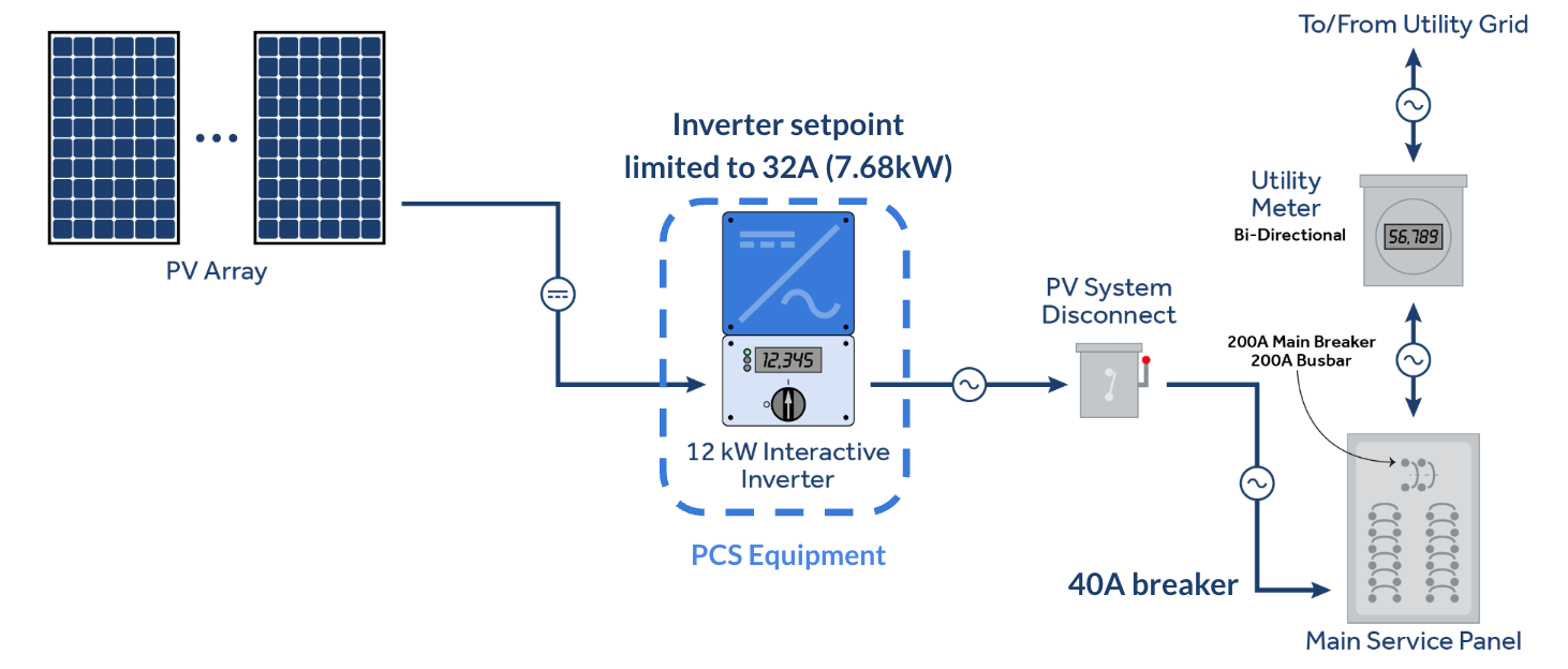
Power control systems (PCSs) can take many forms. One simple example could be a multimode inverter listed as a PCS that is capable of reducing its output current setpoint. Here, an inverter with a 12kW nominal rating is limited to a 32A output to enable interconnection with a 40A breaker. If the inverter operated at its nominal rating, the main service panel could be in an overloaded condition.
PCS Compliance with Article 130 Part II
Multimode inverter-based systems must be in accordance with Article 130 Part II to meet compliance with 702.4(A)(3). Article 130 Part II establishes what a PCS must do, how it must behave, and how it must be documented and marked.
130.60(A) requires the PCS to include monitoring and automatic controls to prevent overload of conductors, power sources, and power distribution equipment. Under 130.60(B), if a failure or malfunction occurs, the PCS must transition to a controlled state that prevents overload rather than allowing an uncontrolled condition to develop.
130.70(A) requires control settings expressed in amperes for each controlled conductor, source, or load, and these settings are treated as a continuous load. Per 130.70(B), adjustable settings can only be accessed by qualified persons through methods specified by the listing.
On the marking and documentation side, 130.80(A) requires the equipment to be marked with PCS control settings, identification of managed loads and sources, and a notice that settings shall only be changed by a qualified person. 130.80(B) requires full documentation of control functions to be readily available to qualified persons, and 130.80(C) requires a directory to be posted where the PCS control equipment is not within sight of the overcurrent protective devices.
The Need for a Third Option: What 702.4(A)(1) and 702.4(A)(2) Couldn't Address
To understand where 702.4(A)(3) fits, it helps to look at the three subsections of 702.4(A) side by side.
702.4(A)(1) covers manual and nonautomatic load connection, where human intervention is required to switch to the standby source. In this case the standby system simply needs adequate capacity to supply whatever loads the user chooses to operate at one time. The responsibility for managing the load falls on the user, not the system.
702.4(A)(2) covers automatic load connection, where the system transfers loads without human intervention. Here the standby source must either be capable of supplying the full automatically connected load, or an Energy Management System must be used to manage the connected load within the capacity of the standby source.
702.4(A)(3) takes a different approach entirely. Rather than requiring the system to be sized for the full load or relying on a separate EMS, it allows a multimode inverter-based system listed as a PCS to actively control overload conditions within a single listed device. This makes it a more integrated and flexible option specifically tailored for modern residential battery and solar installations.
Conclusion
702.4(A)(3) represents a meaningful shift in how the NEC approaches residential standby systems. By creating a dedicated compliance path for multimode inverter-based systems listed as a PCS, the 2026 NEC acknowledges the reality that modern battery and solar installations don't fit neatly into the frameworks established by 702.4(A)(1) and 702.4(A)(2).
For electrical professionals working in the residential space, understanding both 702.4(A)(3) and its relationship to Article 130 Part II is essential to ensuring these systems are installed and documented correctly. As these technologies continue to grow in residential construction, familiarity with these requirements will only become more valuable.
Frequently Asked Questions
Does 702.4(A)(3) apply to commercial installations?
No. 702.4(A)(3) applies exclusively to one- and two-family dwellings. Commercial and industrial installations would need to comply with 702.4(A)(1) or 702.4(A)(2) depending on how loads are connected.
Does any multimode inverter qualify under 702.4(A)(3)?
No. The multimode inverter-based system must be specifically listed as a PCS for overload control. Not all multimode inverters carry the UL 3141 or UL 1741-CRD listing, so verifying the listing before installation is essential.
Who can adjust the PCS control settings?
Per 130.70(B), adjustable settings for overload control can only be accessed by qualified persons through methods specified by the listing. These settings should not be changed by the end user.
What happens if the system shuts down due to an overload?
If the inverter shuts down in response to an overload condition, it cannot restart automatically. Manual intervention is required to restore the system, ensuring that a qualified person evaluates the situation before the system is brought back online.