How to Size Equipment Grounding Conductors per NEC 250.122
Apr 08, 2026
Properly sized equipment grounding conductors (EGCs) ensure that fault currents are safely carried back to the source, minimizing the risk of equipment damage and electrical hazards. Getting the sizing right is crucial for reliable system performance and overall safety and understanding the factors that influence conductor selection can make a significant difference in both design and installation.
EGC sizing for PV systems is directly governed by NEC 690.45. This section gives a direct reference to 250.122, which provides the tables and rules needed to determine the appropriate conductor size based on the circuit’s overcurrent protection. Following these requirements helps ensure code compliance while maintaining safe and effective fault-current paths.
Key Takeaways
- EGCs must meet the minimum sizes in NEC 250.122, with allowances for larger EGCs when complying with sections 250.4(A)(5) or (B)(4).
- Table 250.122 shows conductor sizes by overcurrent rating and material, making copper, aluminum, or copper-clad aluminum wire selection straightforward.
- For PV systems, section 690.45 ensures PV system grounding conductors follow 250.122 with the exception that they do not need upsizing for voltage drop considerations.
- Correctly sized grounding conductors provide safe fault paths, protect equipment, and maintain code compliance.
PV System Conductor Guidelines
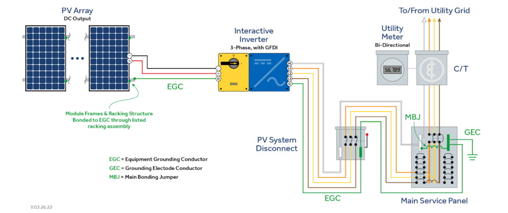
Section 690.45 requires that EGCs in PV systems must be sized in accordance with 250.122. This ensures that fault current paths remain reliable and effective, even in the unique electrical configurations commonly found in PV installations. Proper sizing is critical for system safety and compliance, particularly as PV systems often involve multiple strings and conductors operating in parallel.
Section 250.122(A) establishes the minimum sizing requirements for EGCs made of copper, aluminum, or copper-clad aluminum. The conductor must not be smaller than the size specified in Table 250.122, though it is never required to be larger than the circuit conductors supplying the equipment. The table specifies EGC size based on the overcurrent protection device (OCPD) protecting the circuit. This provides a straightforward method to determine the EGC size.
Section 250.122(B) addresses situations where circuit conductors are increased in size, requiring the EGC to be increased proportionally. However, Section 690.45 provides an exception for PV systems, where this proportional increase is not required for PV system conductors.
In scenarios where no OCPD is installed, such as a single string or two strings in parallel, 690.45 dictates that the EGC is sized as though an OCPD were sized and installed per 690.9.
How to Read and Apply Table 250.122
Table 250.122 provides a clear framework for determining EGC sizes based on the rating of the OCPD. The table breaks down conductor sizing according to the type of material used, including copper, aluminum, and copper-clad aluminum, with sizes listed in both AWG (American Wire Gauge) and kcmil (kilo circular mils). By referencing this table, electricians and designers can quickly identify the minimum conductor size required for a given overcurrent device, ensuring that fault currents are safely carried and equipment remains protected. The table organizes common ampere ratings alongside the corresponding conductor sizes for each material type.
The column on the left lists OCPD ratings, and the row for each rating provides the minimum usable conductor size. If the actual OCPD rating does not exceed the listed rating, the conductor size in that row is sufficient. However, if the OCPD exceeds the rating in that row, the next row down should be referenced to determine the appropriate conductor size. This approach ensures that equipment grounding conductors are neither undersized nor unnecessarily large, providing a balance between safety, efficiency, and compliance.

Determining the Right Conductor Size
Let’s say you have an overcurrent device rated at 80 amps. Referring to Table 250.122, the table indicates that a 8 AWG copper EGC is appropriate, as this rating falls within the 60 to 100 amp range. This ensures that the conductor is large enough to safely carry any fault current that may occur without being unnecessarily oversized. The table provides a straightforward method for matching conductor size to overcurrent ratings, making it easier to select the correct gauge for copper, aluminum, or copper-clad aluminum conductors. By following this approach, electricians can ensure both safety and compliance while avoiding guesswork in determining the minimum conductor size required for any given circuit.
Conclusion
Properly sizing equipment grounding conductors is essential for maintaining electrical safety and system reliability. NEC 250.122 provides clear guidance for selecting the correct conductor size based on overcurrent device ratings and conductor material, while section 690.45 addresses specific considerations for PV systems. Understanding how to read and apply Table 250.122 ensures that fault currents are safely carried, equipment is protected, and installations remain code-compliant. Following these guidelines allows designers and electricians to make informed decisions, balancing safety, efficiency, and practicality in every electrical system.
To get a better understanding of the NEC, take our self-paced course on Critical Updates to the 2023 NEC.